Hardware Setup
This page covers the host BIOS configuration, kernel boot parameters, cable selection, and switch port configuration required before the Mango BoostX™ RoCE AI card can be brought up. Once these steps are complete, proceed to Software Setup to install the driver, configure the network interface, and run the functional test.
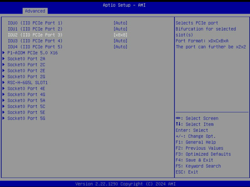
PCIe Bifurcation
Mango BoostX™ RoCE AI requires enabling x8x8 bifurcation on the PCIe slot it occupies. The exact procedure varies by server vendor — refer to your server manual to locate the PCIe slot number and enable x8x8 bifurcation.
For example, on Supermicro servers, modify the following BIOS option:
Advanced > Chipset Configuration > North Bridge > IIO Configuration > CPU1 Configuration
The figure below shows enabling x8x8 bifurcation on IIO PCIe Port 3 in a Supermicro SYS-221H-TN24R server.
IOMMU Setting
Add the following options to the kernel command line in /etc/default/grub, then regenerate the GRUB configuration and reboot. On Intel platforms, use intel_iommu=on instead of amd_iommu=on.
~$ cat /etc/default/grub
...
GRUB_CMDLINE_LINUX="amd_iommu=on iommu=pt"
...
~$ sudo update-grub
~$ sudo reboot
Ethernet Cable Compatibility
The following Ethernet cables have been verified for use with Mango BoostX™ RoCE AI.
| Vendor | Model | Part Number | Type | Form Factor |
|---|---|---|---|---|
| Dell | AEC-Q56DD-400G | 0PP10W | AEC | QSFP56-DD |
| Dell | AEC-Q56DD-400G | 07GGV6 | AEC | QSFP56-DD |
| Innolight | Innolight 400G QSFP-DD SR8 | T-DQ8FNS-N00 | AOC | QSFP-DD |
| Accelight | Accelight 400G QSFP-DD SR8 | AQD400C08509S10 | AOC | QSFP-DD |
Breakout Port Configuration on Switch
Mango BoostX™ RoCE AI is equipped with a single physical 400GbE port, but it operates as a dual-port device — exposing two independent 200GbE interfaces to the host. When connecting the card to a switch, the switch's logical ports must therefore be configured for 200GbE using a 2x200G breakout on a 400GbE switch port.
The example below uses a 400GbE switch running SONiC OS. The exact command syntax varies by switch vendor.
First, check the current breakout configuration of the switch port:
admin@sonic:~$ show interfaces breakout current-mode
+-------------+-------------------------+
| Interface   | Current Breakout Mode   |
+=============+=========================+
| Ethernet0   | 1x400G                  |
+-------------+-------------------------+
Check the .breakout_modes property in the show interfaces breakout command output to verify available modes for the port. This guide assumes the 400GbE switch supports 2x200G mode.
Apply the breakout to split the 1x400G port into two 200G ports:
admin@sonic:~$ sudo config interface breakout Ethernet0 '2x200G'
Do you want to Breakout the port, continue? [y/N]: y

Running Breakout Mode : 1x400G
Target Breakout Mode : 2x200G

Ports to be deleted :
 {
    "Ethernet0": "400000"
}
Ports to be added :
 {
    "Ethernet0": "200000",
    "Ethernet2": "200000"
}
Breakout process got successfully completed.
In the example above, the original Ethernet0 port is split into Ethernet0 and Ethernet2. Each of these can be mapped to one of the two 200GbE RoCE devices exposed by the Mango BoostX™ RoCE AI card.